What we did on Monday laid the groundwork for what we accomplished on Tuesday and Wednesday. We spent almost all of our spare time in the woodshop and metals studio (right up until it closed for break at 5 on Weds.), sanding the edges of and making holes in each panel so that they'd be ready for surface treating.
I also helped Chris out with circuit building after the shop closed. The lights went out in the Arch studios, which was spooky. Because the third floor is haunted. I went home, finished up, and went to bed. Happy Thanksgiving!
Monday, December 6, 2010
Monday 11/22 (10 days left)
Just got back- the plan was that I was gonna work 6-12 (I arrived there with my bags in tow, directly from the airport) but luckily we were overstaffed and I got to leave. To North Campus!
I arrived to find Betsy alone in the Arch studios. Our priority was to ready the panels for stringing on ribbon and painting, which required that we somehow make holes in the top and bottom of each panel and then rinse them clean. Also some of them haven’t been sanded so we need to try and get them done by Wednesday, when the wood shop closes for the weekend.
Betsy and I figured out that the best way to punch holes in the panels would be to poke through them with a hot object, so we cut some copper pieces out of some scrap Betsy had, mounted them in spare handles we found in the metals studio, and then heated them over a blowtorch and poked them through each panel once they were hot enough. We didn’t get a ton of them done, unfortunately, but there was some time yet (and a Heat & Mass Transfer exam in two days).
Thursday 11/18 (14 days left)
We presented our plan and the little progress we have made. Gonna be a crazy coupla weeks. Crit was standard.
We have begun vacuum forming the panels, and they look pretty great- they will need to have the edges sanded down (the band saw is only so precise unfortunately). Should be pretty time-consuming, but they should look awesome.
Looking forward to this weekend, the gang will be working here while I will be out of commission. I hate to strand them like this, but this is my first chance to see my family since September. On the plus side, my mom and I are gonna make this:
Tuesday 11/16 (16 days left)
Crisis Mode! We gotta make a plan! Which is why we are meeting.
We have settled on a final design: we’re going to go with square panels, with the 45 degree rotation. Except they won’t be flat- we are going to CNC a mold onto which we will vacuum-form plastic, creating an undulating surface. The plastic will be cut such that each square will bend on diagonal axis. Here are some pictures:
We think this is a more interesting surface as it lends a third dimension to our surface and will make for more interesting light effects. It also more closely mimics real leaves, which are never completely flat.
We have also settled on stepper motors (one per column of tiles) as the mechanical method of realizing this concept, and will be designing a means of attaching each motor to its respective column. We will work on interleaving, which will allow them to move more smoothly by creating substeps within each predetermined step (there will be 48 in each rotation for the ones we will use). This will address the jerky motion that people took offense at in our first crit of this project.
The top panel of each column will be firmly riveted to the motor (directly or indirectly), and each subsequent panel will be strung along a 3/8” ribbon, which will allow for a natural cascading effect that travels down (and to a lesser extent, back up) each column as it spins. We are still playing around with using one continuous ribbon per column as well as attaching each panel to the next with a short piece of ribbon, as well as surface treatments for the panels. Once we have panels formed and cut we will be able to experiment with those effects.
We have planned out production for this project for the next 2 weeks with objectives for each day. I’ll upload it once someone emails it to me.
Sunday 11/14 (18 days left)
All quiet on the SmartSurfaces front- we were unable to meet as a group this weekend- everyone was tasked with having one concrete direction they want the group to follow before our next meeting, but the architects have a big studio project due early next week, and the rest of us could certainly use some time to focus on other classes (we have other classes?). Hopefully not too much though- not only aren’t they as much fun, but we really need to settle on a direction for this project. We have a lot of ideas and potential forms for this project, but haven’t settled on one for sure. I think John’s description of it was especially apt, so I’ll try and reproduce it here for him and nobody else to read.
“It’s like you guys have all these renderings, and animations, and sketches, and everyone is like, ‘Yeah! You should do that!’”
Now we just gotta choose who to listen to.
“It’s like you guys have all these renderings, and animations, and sketches, and everyone is like, ‘Yeah! You should do that!’”
Now we just gotta choose who to listen to.
 |
| Pat's rendering. Our final direction. |
Thursday 11/11 (21 days left)
After nearly sleeping through the beginning of class on the A&D couches, I arrived just in time to finish and print our executive summaries and present. We were critiqued for our lack of fluid motion, but the renderings once again went a long way in proving our concept. We left our presentation with plenty of questions. The overwhelming feeling that it left us with was that we needed to choose a direction. We continued throwing ideas around during and after we were presenting to the class, leaving us with further exploration to carry out but little time in which to do so. Talking with John and Karl was helpful, but there’s still plenty of work to be done.
Wednesday 11/10 (22 days left)
Our meeting Tuesday was only slightly effective, which left Wednesday to build our module. Simon went to stadium hardware in the morning to buy materials for our frame, and he and I built it together. It was slightly less sturdy than we had hoped, meaning the final modules should probably be smaller and more compact. The rest of the design used boards of MDF at the top and bottom to keep our metal rods in place. The rods were attached to gears that threaded with those on the stepper motors. The motion of each rod was actually quite smooth, as Simon was able to get ball bearings on which each rod could rotate. However, the motion of the panels was quite jerky and inconsistent when connected to the stepper motors, whose discrete angular intervals of rotation were amplified by the use of larger gears.
I worked mostly on construction into the evening, but once the team was assembled in full I was able to help Chris with the Arduino aspect of the project. I was able to write the code that took in information from the PIR sensors and output a signal to the motors to make them rotate. This worked, although we had trouble getting the stepper motors themselves to rotate smoothly. It was definitely nice to do some work with the Arduino this week, as I had been unable to help out much in previous weeks. I’m normally not great at writing programs but this system of hacking and imitating really worked for me- I ran into few problems with the code (which was admittedly simple- here it is)
// Actuate stepper motors based on readings from PIR Sensors// Dan Connors, Design Team 2
//
#include <Stepper.h>
#define STEPS 100
Stepper stepper1(STEPS, 0, 1, 2, 3);
Stepper stepper2(STEPS, 4, 5, 6, 7);
Stepper stepper3(STEPS, 8, 9, 10, 11);
int val1 = 0; // storage for analog output of PIR
int val2 = 0;
int val3 = 0;
int pirSensor1 = 0; // the passive infra red sensors will be plugged
int pirSensor2 = 1; // at analog pins 0, 1, 2
int pirSensor3 = 2;
int THRESHOLD = 5;
void setup() {
Serial.begin(9600);
stepper1.setSpeed(100); // motor speed = 30 RPM
stepper2.setSpeed(100);
stepper3.setSpeed(100);
}
void loop() {
val1 = analogRead(pirSensor1); //read values from PIR sensors
val2 = analogRead(pirSensor2);
val3 = analogRead(pirSensor3);
while ((val1 >= THRESHOLD) && (val2 < THRESHOLD) && (val3 < THRESHOLD)) {
stepper1.step(10); //turn on motor 1 if PIR 1 senses motion
stepper2.step(0);
stepper3.step(0);
val1 = analogRead(pirSensor1); //read values again- keeps motors going
val2 = analogRead(pirSensor2); //if motion hasn't stopped
val3 = analogRead(pirSensor3);
delay(125);
}
//repeat for each possible scenario of PIR sensors
while ((val1 >= THRESHOLD) && (val2 >= THRESHOLD) && (val3 < THRESHOLD)) {
stepper1.step(10);
stepper2.step(10);
stepper3.step(0);
val1 = analogRead(pirSensor1);
val2 = analogRead(pirSensor2);
val3 = analogRead(pirSensor3);
delay(125);
}
while ((val1 >= THRESHOLD) && (val2 >= THRESHOLD) && (val3 >= THRESHOLD)) {
stepper1.step(10);
stepper2.step(10);
stepper3.step(10);
val1 = analogRead(pirSensor1);
val2 = analogRead(pirSensor2);
val3 = analogRead(pirSensor3);
delay(125);
}
while ((val1 < THRESHOLD) && (val2 >= THRESHOLD) && (val3 >= THRESHOLD)) {
stepper1.step(0);
stepper2.step(10);
stepper3.step(10);
val1 = analogRead(pirSensor1);
val2 = analogRead(pirSensor2);
val3 = analogRead(pirSensor3);
delay(125);
}
while ((val1 >= THRESHOLD) && (val2 < THRESHOLD) && (val3 >= THRESHOLD)) {
stepper1.step(10);
stepper2.step(0);
stepper3.step(10);
val1 = analogRead(pirSensor1);
val2 = analogRead(pirSensor2);
val3 = analogRead(pirSensor3);
delay(125);
}
while ((val1 < THRESHOLD) && (val2 < THRESHOLD) && (val3 < THRESHOLD)) {
stepper1.step(0);
stepper2.step(0);
stepper3.step(0);
val1 = analogRead(pirSensor1);
val2 = analogRead(pirSensor2);
val3 = analogRead(pirSensor3);
delay(125);
}
while ((val1 < THRESHOLD) && (val2 < THRESHOLD) && (val3 >= THRESHOLD)) {
stepper1.step(0);
stepper2.step(0);
stepper3.step(10);
val1 = analogRead(pirSensor1);
val2 = analogRead(pirSensor2);
val3 = analogRead(pirSensor3);
delay(125);
}
while ((val1 < THRESHOLD) && (val2 >= THRESHOLD) && (val3 < THRESHOLD)) {
stepper1.step(0);
stepper2.step(10);
stepper3.step(0);
val1 = analogRead(pirSensor1);
val2 = analogRead(pirSensor2);
val3 = analogRead(pirSensor3);
delay(125);
}
The panels themselves were squares, but to make the module more visually interesting we rotated them 45 degrees in the plane of the surface so that they partially overlapped with those in the neighboring rows. We didn’t have enough acrylic to make the tiles as well as some of the mock-ups we had used, so we spray painted some chipboard. This was less effective, but served our purposes well enough.
Sunday 11/7 (25 days left)
We met Sunday to discuss where to go with our project- Pat and Chris had made some sample tiles with acrylic and mylar, which looked really great (see photos below). Our discussion was mainly formal, as we debated the merits of various tile shapes and sizes. This did, however, force us to touch on aspects of mechanization of the module we were building for Thursday, as the effects we were interested in producing would dictate to an extent what we wanted to build and how we would build it.
We assigned roles for everyone to fulfill before our meeting Tuesday by splitting into mini-teams that would focus either on rendering or building. Our goal was to make a larger, more functional, and sleeker version of the array of panels we made last week and to have renderings of other possible tile designs.
We assigned roles for everyone to fulfill before our meeting Tuesday by splitting into mini-teams that would focus either on rendering or building. Our goal was to make a larger, more functional, and sleeker version of the array of panels we made last week and to have renderings of other possible tile designs.
 |
| Chris "Biceps" Sketch, rockin' panels, Simon "Oreos" Rolka |
Thursday 11/4 (28 days left)
Our presentation was well received, due mostly in part to Pat’s renderings. We have decided to stick with the rotating tile installation, and after lunch we discussed formal and functional problems. Formally, the discussion centered on what the tiles should look like. Functionally, it was a matter of determining how to actuate the motion and build the framework. We decided to meet again Sunday with “leads” on both fronts.
Wednesday 11/3 (29 days left)
I spent today working on assembling the model for the radial tessellation. It didn’t work. Here’s why:
1. Too Small. We made the tessellation to have a 5.5-inch diameter. This was not only smaller than most of the installation would end up being, but it made assembly much more difficult. I had to assemble the model in one go, and were I to have another shot at making this work I’d have done a few things differently, most importantly I’d have assembled it in a different order (one more time-effective).
2. Inexact. The file we used was traced from an illustrator file, and had we taken the time to make it ourselves, I think it would have been more accurate and easier to assemble. I ran into problem making all the pieces fir together, as it had been taken apart once or twice. Were I to be able to do it again (we are going to abandon this desgn) I would make the design on my own and start assembly from the sheet immediately after its cutting.
3. Not enough springs. I went to Home Depot this afternoon to get more of the right kind of spring (Diana had bought a variety pack earlier in the week) but they only had springs that were far too large, and I would have needed to buy 24 variety packs to get the correct number of springs (shockingly, Home Depot didn’t have 24 of them and I didn’t have $80).
4. I started too late. That’s not to say that all of this could have been avoided, but I think I would have made more progress had I been able to start earlier. Luckily, this prototype was secondary to the one that the rest of the team worked on, and theirs worked. They actuated the “spinning tiles” wall installation using mylar-wrapped pieces of chipboard on a Merkur frame that were connected by gears to a number of servos (one for each column, three of which we were able to actuate). This served as a proof of concept for our idea to have a wall’s worth of tiles that rotated as people walked by, which Pat rendered. (see "Photos!" post)
Tuesday 11/2 (30 days left)
Started building my prototype today- hopefully I’ll finish it too! I tried building it by hand out of chipboard, which was largely unsuccessful, so then I worked with Betsy on a cut file so that I could make a stronger, more exact one. I’m pretty optimistic, but actuation might be an issue. We’ll see I guess.
Sunday 10/31 (32 days left)
We met today to continue workshopping our designs and ideas. Here’s the meeting as summed up by Betsy:
“So here's just a recap of all the sorts of ideation we went through and the plan for this week.
Chris came in with the attached syringes and tubing and had found a way using water (when all the bubbles are removed) to have a pushing and pulling type mechanism that would allow for further actuation of the solenoid. The benefit would be a fairly silent mechanism and a nice ambient pulsating effect when the wall/piece was not coming in contact with direct interaction. We would still likely need a solenoid for each part still unless we could rig multiple ones to go off at the same time, but we also would face the issue of having to mechanize some sort of shutoff valve. We discussed that this was perhaps even more complicated than something like gears and also high risk due to the issues that would come about from bubbles in the water and parts popping off (which would be a pretty considerable problem if we had to go and fix malfunctioning parts while it's on display at pfizer). Still it is fairly cheap and silent. Another issue would be how many of these we could control with one arduino. There are only 13 digital pins and 6 analog pins (and I would imagine some of those would already be used by whatever sensors and power we needed for the breadboard). We will be purchasing an arduino mega to see if this would be of benefit to our design.
For a potential prototype for this week, we discussed a possible lightbox display. We also talked about creating our own solenoids with some non-conducting type tubing material and wire/springs wrapped around that. It's possible that we might be able to create a push-pull / dual-direction solenoid. At this point in the meeting we thought it was important to focus on simple squares and mechanize those and deal with the design later. But, in light of the professors saying that we should approach this week as what could we do if the entire project was due in one week, it made a little more sense to focus on the physical form too.
Simon then presented his idea of a folding extender much like a "lift" (kind of like those folding stands for air drying clothes - anyone?) that would be made up of criss-cross parts that could fully extend or fold back up to lie almost flush. We could make them different lengths to help create a series of levels that the panels could extend out to, helping with the kind of random design we want to appear. This would definitely help actuate the pushing motion, but would still require some sort of elastic thread or spring to bring the piece back to it's original flush state.
Then Diana showed us a small model she had made of four chipboard squares on top of springs with a small blue fan under them. This went off of the suggestion we received in class to possibly use computer fans and have air blowing at people and playing with a variety of both visual and sensory or perhaps "felt" interaction. Unfortunately the fan had very little effect at moving the pieces and they just sort of slightly wiggled around. This did get us talking about creating some sort of walled area that could trap maybe hot air and release it at people as they walked by and played around with our "window wall."
We decided to revisit the idea of the "agave" wall that had these scale, like, tiled elements that could angle outwards. We starting calling these flaps and discussed the benefits to inverting the direction and having these pieces hinged at the top (instead of the bottom) and open out and upward (instead of out and down) so that people could look more straight and up into in instead of only seeing down into the mechanism. This would also likely allow for more diffuse light to come through and would provide the pullback of gravity instead of having to use some other sort of mechanism. We also started to discuss that if we had scale like flaps angling out instead of pixel designs, it might be smart to have some sort of three-dimensionality to the actual flap pieces. We could probably achieve this with a frame wrapped in fabric and either given form by air or some sort of stuffing inside the piece.
We were concerned over using way too many mechanized parts (one solenoid per flap / pixel / piece thing didn't seem as well designed as our professors might like). We talked about having "dummy" panels connected to a live panel that would sort of pull along the surrounding pieces. Pat drew a little sketch of a way we could have the fixed pieces attached to multiple live panels in a set pattern. We wondered if we could alternate which inactive panels are dragged by the fixed panel. We would definitely have to play around with that but it would help it be less predictable so that someone doesn't notice one panel always moves and the ones around it are dragged along. We could also have some sort of rotating piece that would push all the pieces out, one by one, as it rotated. A full turn would mean all pieces were pushed outward in some way.
Pat then presented the idea of a multi-layered surface that would have translucency and each layer would react to a different stimuli (ei. sound, motion, heat, etc.) The angled panels would be on the outside and you would have to get close enough for the panels to lift up to see the other motions inside. We worried this would leave the surface fairly undiscovered most of the time and also be incredibly difficult to hide the mechanics between each layer. There was also some brainstorming on rotation, and fanning out elements like a flower, some sort of spinning or crossing over of colors. While we definitely should play around with color in our piece, I think it's important not to lose sight of a textured, dynamic wall not just sliding color panels.
There was more talk about filtering light, scattering light, diffusing it. We could have spinning pieces with a different color on each side, we could use a dyed fabric that wasn't consistent (sort of gradient like) to give an added visual pattern and overlay. We could use pearlized / opalescent type stuff like that shoalfish video. We could spray paint over some screen type thing to give more pixelated and see-through color on acrylic. We could also maybe pierce holes into a panel to allow for light patterns to play on the floor and opposite wall while still having the diffuse light outlining the pieces.
We talked about using hooks instead of hinges for the angling-out design. We also discussed the importance of maybe doing material studies like a frame with fabric, spraypaint techniques, lightness of material in relation to the mechanisms.
At this point we felt we had come up with a lot of ideas and directions to go if anything didn't work out, but it was super important to have concrete, working prototypes. The plan is to have Pat and Chris work on the "agave" prototype and find a way to mechanize that and Dan and Betsy will work on getting the "radial tessellation" wall to work so that we have a clear prototype of both designs we seem to be talking about at the moment. Simon will help sketch things out and bounce between these two groups helping where we need him to (and probably giving Betsy and Dan crash courses in Rhino). Diana will be submitting our budget to John (acrylic, 10 small solenoids, 5 large solenoids, one mega arduino, and I think perhaps some other sensor). Dan might pick up some springs from the hardware store. Diana could also help with material studies or prototypes of the mechanisms we want to use, and should probably make sure we have some sort of record of all the prototypes we are making. That way we can upload pictures to the flickr and hopefully put more videos on the youtube channel.
We will be meeting on Tuesday night to see where we're all at with these prototypes and fix anything that isn't working and decide our plan for what we want to finalize wednesday night for class Thursday. I believe John asked for our installation sites pretty much immediately so if Pat and Simon can get any photos they need from Diana and maybe let John know, that would be great.
Sorry for the long email, team snax, but it was a productive meeting for sure! :)
-Betsy”
I thought this was a very comprehensive summation of our meeting. I felt good leaving the meeting because we had two major designs that we were working on- it was good to settle on a few definite directions. Pat and I were both tossing different ideas and inspirations at the end of the meeting, so hopefully he and I will be able to make a few extra prototypes for presentation on Thursday. My hope is to have the physical models for the top two prototypes ready by the end of Tuesday so that we can actuate Wednesday. Or even get most of both done Tuesday and continue workshopping these and other designs on Wednesday.
Thursday 10/28 (28 days left)
I arrived early after an interview with Rogers Corporation (which went pretty well, thanks) and accidentally woke a lightly sleeping Chris, who’d apparently been there all night. He and I tried to get his program to run on my computer (as his was not communicating with any of our Arduinos), but we were unable due to my perplexing inability to augment the Libraries in my Arduino folder. Luckily, we were able to run it on Betsy’s computer and had a successful demo. Here’s a link to videos of various actuations we achieved: http://www.youtube.com/user/ducktrap2 (thanks to Diana for setting up a YouTube account). Our demo and presentation were well-received, especially Pat’s renderings of different patterns a grid of square cells could make when pushed out or pulled in individually. It felt great to have something functional, and we broke for lunch a satisfied group.
After lunch Bill Phillips, the research student using our class for his thesis, gave us a talk. He told us about the role that evaluations play in his and in the professors’ estimations of our learning experience in the class. It was interesting to see not only the differences in how people rated themselves as opposed to their teammates as well as how students from different disciplines rated themselves and their teammates. It seemed that the engineers were hardest on themselves, and that the class as a whole was willing to rate themselves higher than their teammates. We also discussed the role of phrasing in determining the ways in which certain students rate themselves: it seemed that the engineers were wary of the use of “design” and “artistic” in two of the five questions asked by the survey.
After this presentation we reassembled the group to discuss next steps. We set to brainstorming and had a lot of great ideas but got bogged down in determining how to mechanize our ideas in as simple and effective a way as possible. When the professors came around to discuss our progress, they told us (in not so few words) that the best way to resolve this would be to prototype and decide based on which prototypes were most effective, which is what we planned to do. Methods of actuating the push and pull of panels in our grid included air and water jets/pumps, magnets, springs, strings, and a mess of servos and DC motors. Which is just what we decided to do.
Photos!
 |
| Simon's Merkurpult (week of 10/28) |
 | |
| Plan. |
 |
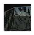
| Our semi-functional other module. (Week of 11/4) |
 |
| FORESHADOWING |
 |
| SPRANGS. Couldn't get enough of the right kind to make this happen. |
 |
| The bare bones of the radial tessellation I was working on. Sketches to come (I hope) |
 |
| Better late than never- our team design! (Week of 10/21) |
Sunday, December 5, 2010
Tuesday-Wednesday 10/26-7 (37-36 days left)
Group meetings were disorganized and lacked motivation. Discussion would last a few minutes but would fade to aimless chatter before anything of value was said.
When crunchtime came around, we were able to get something that worked. Most of our sensors (i.e. the ones we had the correct parts and data for) worked on their own, and we had a slight issue with actuating them in tandem, but we were able to make the solenoids work with the help of the external DC power supply and the LEDs with prompts from the Ultrasonic Range Finder. While we had working programs for the Pressure sensor and tilt ball sensors, neither made it into the demo; the voltage across the pressure resistor was too high and the device would just heat up and not produce an LED response upon being pressed, and the tilt ball sensors were inaccurate and therefore not worth demo-ing.
The form this ended up taking was as follows: a Merkur stand with LEDs lining the vertical piece of the structure and a rotating lever that accentuated the upward and downward motion of the solenoids. The solenoids, when actuated, would push down on one end of the lever, pushing the other end up to approximate our desire to have “pixels” in some pattern that when pushed or pulled would allow light to come from a light source behind the surface (we would likely mount it in front of a window). As the URF read in values of increasing proximity, the LEDs on the vertical Merkur piece lit up from bottom to top. This was as complicated as we were able to get, but we felt it adequately demonstrated our desire for the surface to react to multiple stimuli in various ways. Pictures will come!
Monday 10/25 (38 days left)
Continued working on the sensors today- had some trouble with the accelerometer. It seems I may need an ADC converter to make it work on the Arduino- it says on the parallax website that there’s an onboard one but all the schematics I can find are poorly labeled and seem to include one. Look out Chris, here comes an Arduino question!
Wednesday 10/20 (41 days left)
Doncha just love anachronism? Forgot to post this one:
We met at our earliest convenience (Wednesday, due to people's being away for fall break) to write our contract for the Team Design assignment. Here are the highlights:
Missions
- functional (duh)
- well-designed (sleek and elegant)
- uses element of surprise (for users as well as for us, i.e. we don't know how it will evolve)
- function informs form (i.e. we won't make the same mistake as with the visor- we don't want to constrain our design to too narrow a situation/problem)
Vision (of a team that is/will . . .)
- Efficient
- Maximize efforts and skill sets of all members
- Communicate well
- Allow for ideas to flow naturally
Values
- Democratic, consensus-based decision making
- Communication
- Maintained Inspiration
- Respect for other obligations: Studio, Senior Design, Exams
Goals
- Communicate well
- Substantial weekly improvements
- Component testing (NOTE: this was misunderstood in the final critique. "Component" here refers to smaller subsystems of our larger project, such as testing the motion sensors on a standard circuit. This does not refer to buying electrical components and playing around with them, which we did in a limited manner.
- Research precedents throroughly
- Learn new skills
And here's our SWOT analysis:
"We are a unified and dedicated group: we are cooperative and respond well to constructive criticism, and are resourceful with what materials are available to us. We brainstorm well, and as a result we often undertake imaginative projects with a high level of conceptual development and pursue these projects with a fearless attitude and a committed work ethic. We are able to self-motivate as a group; we respond well to the encouragements of other team members.
Our group’s most notable weaknesses all relate to timing. We often attempt to do more than is possible in the given amount of time, and if not we budget the time we do have poorly. Our process for assembly has been inefficient, as we put each entire model together at once, as opposed to testing before interfacing with other components. We are also occasionally prone to poor communication skills, as some team members are often uninformed of progress by the remainder of the team after having missed a meeting. Other issues we have had arise from lack of experience in Digital Project and biomimcry research.
Opportunities for our group consist mainly of as-yet untapped resources: we can take fuller advantage of our access to the metals studio and the tools therein, as well as relying even more on renderings, drawings, and other media of communicating our ideas and models to the class in critique. We also are fortunate to have a team member who works in the patent industry, should we invent a new mechanism or device.
External threats that could impact this team’s performance will consist mainly of scheduling constraints as other classes become more demanding and exams approach, so we will need to plan our time very efficiently. Acquisition of parts and components for the construction of our surface could also slow down our progress in making this project a success if they do not proceed in a timely manner, meaning that the sooner we can determine what we need the less likely the purchase and delivery of these items will impede the development of our finished surface."
We also agreed on a decentralized team structure that enabled everyone to work in different capacities and contribute to all portions of the project, knowing of course that some peoples' past experience and skills would to some extent determine the way in which we would choose to utilize them. For example, Chris would be in charge of Arduino-related aspects of the project, and Diana would be in charge of documenting the group's progress from day to day. This would leave the rest of us to take charge of mechanization and anything else that would need doing.
Sunday 10/24 (39 days left)
Today we met in the Dude to start planning our final project. The general schedule we were given asked for a $200 budget and an operational prototype for Thursday, and per Karl’s morning email we started small (he said to stick to what works and design based on functionality). We laid out and listed all of our new toys that had come in the mail and used those as a jumping-off point for what our product could become. This was marginally successful, and we ended the meeting by assigning each member of the group who was capable two of our new sensors/components to wire and code: Simon had the force-sensitive resistors and the camera, Chris had the solenoids and the Temperature/Humidity sensors, Patrick had the Ultrasonic Range Finder and the microphones, and I had the accelerometers and data logger.
Our brainstorming focused on the interactions we wanted users to have with our project based on what we could accomplish with our newly acquired sensors. Simon wanted something ambient- ideally the users would be unaware of the product’s presence until a response from the surface is provoked. We also talked about trying to incorporate our previous design (the triangles of project one) into this surface, or at the very least a folding/revealing mechanism.
I went to DL1 and assembled the data logger according to the instructions online. This took a while and I accidentally burned my finger but I was able to finish it before my ride had to leave. I didn’t get to code anything for it, but tomorrow I should be able to take care of both that and the accelerometer. I feel optimistic that we can make a pretty cool (and functional) prototype this week, and look forward to finding out how this project evolves.
Thursday 10/21 (35 days left)
We were asked to order some toys to play with for next week- we all looked around on the Parallax, Sparkfun, Adafruit, and Jameco websites and compiled a list of sensors and components we wanted. Here's what we got:
3 solenoids
data logging shield for arduino
flex bend sensor
5 tilt ball switches
2 force-sensitive resistors
temperature/humidity sensor
2 electret microphones
arduino protoshield
CMOS camera
3 stepper h-bridges
CO2 gas sensor
ColorPAL color & light sensor
I was most excited about the data logger and the accelerometer. The data logger would allow us to track and analyze data and actuate based on trends as opposed to instantaneous data values should we want to. The accelerometer would allow us to track motion we actuate and further actuate the surface based on that.
Our field trip today was a journey to the botanical gardens. We were given a tour by David Michener that covered the majority of the indoor facility and which gave us largely formal inspiration- the two most intriguing plants we found were the “Swiss Cheese Plant”, so named for the characteristic holes in its leaves that allow light to reach the lower leaves, and the aspen plant, whose leaves are table to bend and twist towards light so as to increase absorption. Here are some pictures:
 |
| Aspen? Mmmmmm, California. |
 |
| Goes great with ham on rye. |
HEY JOHN!
Get ready- this is the week I upload all the blog posts I've written but not posted, plus the ones I've neglected to write the past three weeks. If you hadn't already noticed I'm slightly verbose, so ready your reading glasses.
Subscribe to:
Posts (Atom)